Safety nets that look correctly installed can still fail to protect an operative in a fall. The reason is rarely the net itself or the anchorage. It is the clearance geometry below the net — the space available for the net to deflect under the dynamic load of a falling person without the person striking the ground or any structure beneath. Where this geometry is wrong, the net is decorative rather than protective. Getting it right is one of the most consequential decisions in any fall protection installation.
What clearance geometry actually means
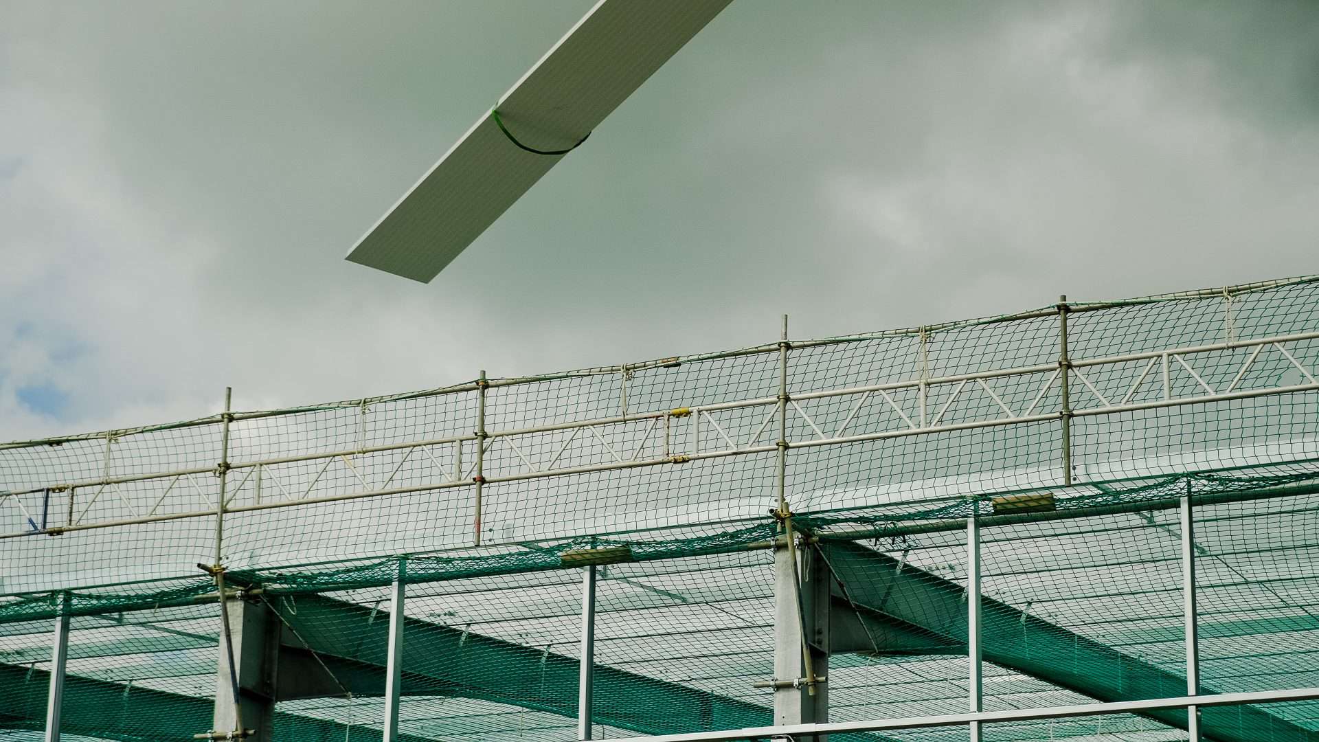
When a person falls into a safety net, the net does not stop them instantly. It deflects, absorbing the energy of the fall over a distance and a duration. The deflection is what makes the system safe — a net that did not deflect would arrest the fall with forces that would themselves cause serious injury. The space below the net needs to be sufficient for this deflection to occur without the falling person making contact with anything below.
Clearance geometry is the calculated combination of the net’s deflection under load, the height of the fall, the position of the net relative to the person, and the obstacles below. A correctly designed installation has enough clearance for the net to do its job. An incorrectly designed installation does not, regardless of how well the net itself has been installed.
BS EN 1263-1 and net classification
Safety nets used on UK construction sites are classified under BS EN 1263-1 and 2, which defines the energy absorption requirements, mesh size, dimensions, and other characteristics of safety nets. Different net classes have different deflection characteristics under load. The class of net specified for a particular installation has to be matched to the fall conditions anticipated and the clearance available.
Specifying a net class without considering the clearance below produces installations where the wrong net is used in the wrong place. Red Safety Netting’s installation design includes net classification matched to the actual fall conditions and clearance constraints of the project, not assumed against a generic standard.
The fall scenarios that determine clearance
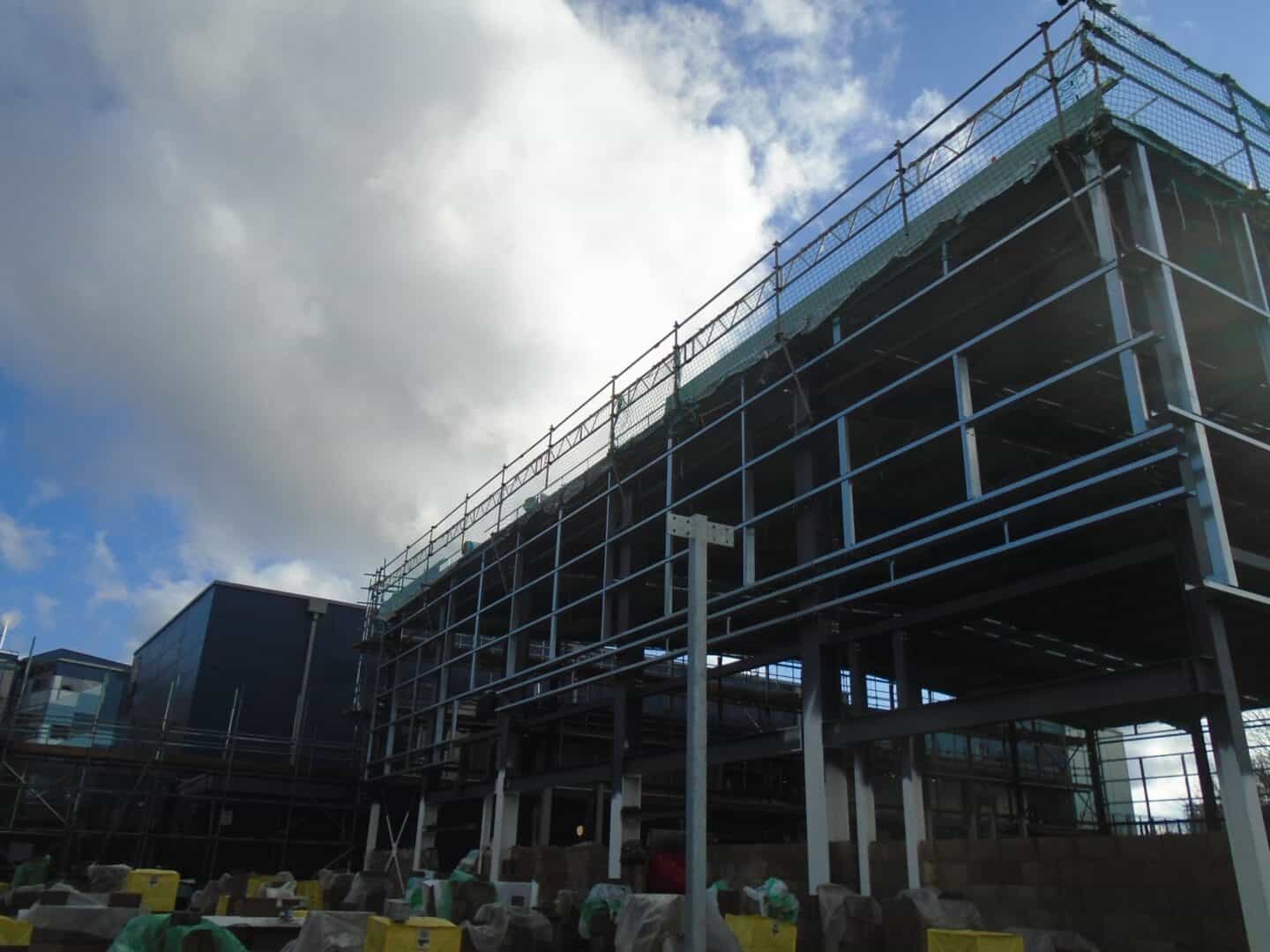
On a typical new build commercial site, the fall scenarios that drive clearance calculation include falls from the eaves during roofing operations, falls from gable end work, falls from access points to the roof, and falls from edge work where edge protection is interrupted for material loading. Each scenario presents different geometry — different fall heights, different positions of the net relative to the operative, and different obstacles below.
The installation design needs to address these scenarios specifically rather than assuming a generic worst case. A net positioned correctly for falls from the eaves may have insufficient clearance for falls from gable end work if the geometry of the gable changes the relationship between operative and net. These are the kinds of details that matter on every individual installation.
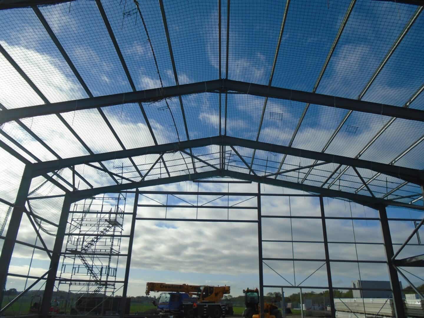
Obstacles below the net
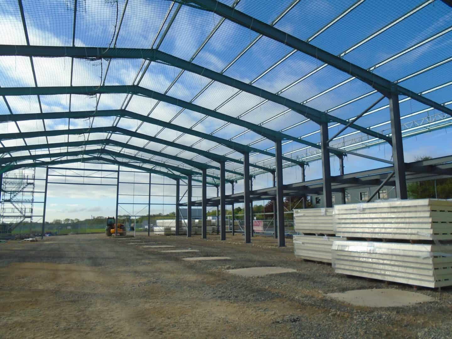
Clearance geometry depends not just on the distance to the ground but on what is in the space between the net and the ground. Stored materials, scaffold structure, internal partitions under construction, and plant on site can all reduce the effective clearance to a value below the geometric distance from net to floor. An installation designed against geometric clearance that does not account for obstacles in the deflection path is an installation that may not perform.
This is one of the reasons safety netting installations need to be designed for the actual site conditions, not against a template. Conditions change as the build progresses — materials are stored, scaffold lifts are added, internal partitions go up — and the clearance calculation may need to be reviewed during the life of the installation.
Anchorage and the deflection assumption
The deflection characteristics of a safety net assume the anchorages will hold. An anchorage that fails or moves during a fall changes the deflection geometry entirely, typically increasing the effective fall distance and the consequences. Anchorage selection, placement, and load testing are therefore part of the clearance question, not separate from it.
Red Safety Netting’s installation procedures address anchorage as part of the integrated design. Anchorages are specified for the structure they are connecting to, load-tested where required, and documented as part of the installation record. The deflection geometry is calculated against verified anchorage performance, not assumed.
Documentation that captures the design
On any safety netting installation, the documentation has to capture the design assumptions — net class, anchorage configuration, calculated clearance, fall scenarios addressed — so that the installation can be verified against them and re-verified if conditions change. Under FASET protocols and the Globe Group’s ISO 9001 quality management framework, Red Safety Netting installations are documented to this standard.
For principal contractors, this documentation is what supports their CDM 2015 and HSWA position. If a fall occurs and the net performs as designed, the documentation demonstrates that the design was appropriate. If conditions changed during the installation and the design was not updated, that is a different conversation — but at least the original design intent is captured.
Inspection through the installation life
Clearance geometry can change after installation if site conditions change. Materials stored under the net, additional scaffold lifts, or modifications to internal partitions can all reduce effective clearance. Periodic inspection during the life of the installation needs to verify that the clearance assumptions still hold, not just that the net itself is intact.
Talk to Red Safety Netting
To discuss fall protection design and installation on your project, contact Red Safety Netting on 01223 890727 or email enquiries@theglobegroup.co.uk.